Yesterday I wrote up a post that I had on my list of the last couple of years but never got around to. My all time favorite project, building a windmill and some of the stories behind it.
I made a promise to open source the design, and today I finally hope to make good on that promise. This comes with a word of warning though, I am flooded with work at the moment so I do not have the time to make this a picture perfect release. I am making a lot of assumptions about the skills of the people that would attempt an undertaking like this and if you are in doubt you probably should not even try this. In some ways releasing this scares the crap out of me because the possibility of someone getting hurt is > 0, even simply building this (without ever using it) is not without risk. I almost lost a bunch of fingers mounting the magnetic drum, so please take this as a warning (and I really like my fingers, and I’m really careful). A single ‘neo’ magnet is already dangerous, 18 of the mounted to a chunk of steel is a formidable thing. No pretty pictures today, just dry technical stuff.
Welcome to this terribly messy jumble of bits and pieces that I recovered from my subversion
repository. It's a snapshot of the state of the project after the machine was finished.

I wished I could say I was proud of the result but that's far from true.

In this archive you will find a number of directories with a fairly large number of files
that should in theory allow you to re-create some or all of the parts that went into
making the Big Blue Windmill that is on display at

    https://jacquesmattheij.com/how-to-make-a-windmill

and some of the tools (specifically, the software to drive the plasmacutter/3D mill and to
visualize the toolpaths).

I promised I'd open source the design and this is my attempt at doing just that. Here are some
of the caveats regarding this design:

 (1) Only *ONE* of these was ever built. That means there are likely design flaws, errors and
     omissions that will cause problems in the first few hundred copies made according to these
     (possibly incomplete or inaccurate) plans.

 (2) I'm releasing this information as a private individual and accept absolutely no liability
     of any sort with respect to this release of information. If you build this machine even
     if it is exactly according to these plans then I do not warrant anything whatsoever. These
     plans are provided 'as is' without any warrants as to suitability, accuracy or even being
     fit for reproduction. If you, your pet, your children, spouse, innocent bystanders or any
     other person or good are harmed, lost, killed or damaged because you use these plans then
     *YOU* accept full responsibility for that.

 (3) These plans are now 8 years old. 3 of those years the windmill was operational in Northern
     Ontario, Canada. The climate there is fairly harsh but there may be local factors where
     you live that affect the design in a negative way. If you don't do your research before
     you embark on building a machine like this then you will likely end up doing damage to
     yourself or others.

 (4) Windmills of this size are *NOT* toys. The amount of energy in a machine this size moving
     at full speed is downright scary, you could very easily do considerable damage to
     structures and people (including killing them) in a radius of 2 Km (1.3 miles) around the
     location of the tower, possibly even further if you put it on a really tall tower. Keep
     this in mind when you experiment with windmills, there is absolutely no fun at all in
     turning a school bus into a giant shish-kebab by hurling an 8' windmill blade through it
     at 400 miles per hour.

     If you do not understand the engineering and manufacturing challenges of building
     something like this then please go and collect poststamps or find another hobby that is
     safe and within your area of expertise. I have a large amount of experience designing
     mechanical stuff and in fabrication and the complexities and challenges involved in
     windmill design - as well as the enormous energies involved - have left me with nothing
     but respect for the wind and its ability to destroy things and to surprise you.

 (5) If this is your first windmill by all means stop now and build something smaller and
     simple first, see

            http://www.fieldlines.com/

     the people there have tons of experience making machines that are much simpler to
     reproduce than this one. This machine is complex, far from perfect and requires a lot
     of tooling and expertise to build and to operate safely. Please take this serious.

 (6) This project, the code and the design is licened under the:

     http://sam.zoy.org/wtfpl/

     Wtpfl license.

Now, with that out of the way, and assuming you are still reading:

This package partially (there is some stuff missing, but if you can't figure that bit out
you really shouldn't be building this) describes the bits and pieces that are required to
build a horizontal-axis 2.5 KW design power 16' wind turbine.

Such a machine is suitable for the power requirements of a single home assuming there is

  - enough wind

  - some kind of backup system (for instance, solar power or a diesel generator)

  - a battery pack

  - an inverter

  - a rectifier to take the AC current from the windmill and turn it into DC

A windmill is part of a system, it is not a stand-alone source of usable power and you need
to take this into account.

The windmill itself (professionals (and snobs) call them 'turbines' because they don't mill
your mustard seeds but here in .nl where I live we call water pumpers windmills and so on
so forgive me if I stick to the term windmill, if you have trouble with that then please
imagine it milling the wind) consists of several structural elements that give the machine
a way to attach to the post that it is mounted on, a main shaft, a rotor, a stator made
up from laminates, a governor, a set of blades and a tail.

the directory tree that goes with this package contains:

cad-drawings         All of the .dxf files that I could find
cutter-jobs          The job files ready for transmission to the homebrew plasmacutter/mill
programs             Software used to design the various parts in a parametric way

Here is a verbal description of all the parts/construction of the windmill, all the bolts are
copiously covered with 'never seize' aka copper grease. You will likely balk at the price when
you buy this stuff but you will balk a lot worse when you want to dissassemble the machine
three years down the line if you don't use it. I have not listed the 'small fry', nuts and
bolts, I assume you're smart enough to figure out that if a hole is threaded for 3/8" that
that's the bolt that goes in there. All the bolts used in the construction are regular grade
hex head inox or anodyzed. Bolts that are subject to vibration are held down with locktite
blue.

There is no handholding here and I'm afraid I can't offer you support if you decide to build
this machine. So be prepared to do some figuring out and fixing if you find something in this
description is wrong or if you think you have a better plan. Most of the sizes used are in
*Imperial* measurements, I was building this machine in North America. With a little bit of
work you can adapt those measurements to the metric system, I'd go for a drum outer diameter
of 300 mm and work back from there if I wanted to build this machine using metric components.

- support structure
  (1) Main housing, upright tube
      4" od, 1/2" wall technical tubing, 12" long, hole milled in the center for the slipring
      assembly (bronze riders on trespa making good contact with sliprings around the shaft
      that connects to the tower stub) milled out at a 15 degree angle at the top to accept (3)
      which will be welded in place. The bottom end of this tube is milled out to accept two
      bearings id 2", these bearings are locked in place using lockrings, which are placed
      in a groove turned into the wall of the tube.

  (2) The support shaft.
      This shaft is hollow so the wiring for the 3 phases can pass through
      the center and be connected to the sliprings. Another bearing is seated at the bottom
      of this tube. The shaft itself will be stationary with respect to the tower, so the
      machine rotates around it as it orients itself with respect to the wind.

  (3) Main housing, horizontal tube
      4" od, 1/2" wall technical tubing, 18" long 2 bearing holes cut out at each end. Bearings
      are 2" id which will accept the main shaft (4), again secured with lockrings placed into
      a groove turned into the wall of the tube.
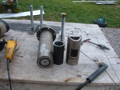
Shows these components before welding up, in the picture you can see that the shaft and
the stator mount are already in place.
(3a) the statormount
See the file spacerring.job
(4) The main shaft is a 2" solid high tensile steel shaft, a (4a) 3/4 " steel disc with a
hole od 4", id (of course) 2" is welded on to the end sticking out the front onto which
the governor base plate will be bolted. The end of the shaft is threaded with 3/4"
thread to accept the central post along which the rider will move.
(4a) Disc welded to the main shaft, 3/4" mild steel, 12 hole pattern to mate with magnet drum
and governor base plate (13)
(5) 4 bearings, 3" od, 2" id (I used SKF but this is not overly critical, I'd use a quality
brand though because a bearing failure can have dramatic consequences).
(6) Lockrings to secure the bearings in their spots
(7) A stub that matches the tower inner diameter, with a hole large enough to accept the
shaft. Keep a bit of space here, secure the machine against lifting (yes, that can
happen, don't let it happen to you) by bolting it down from three sides with bolts
that are threaded trough the stub *into* the shaft.
- The stator
(8) 48 sheets of mild steel (preferably with good magnetic properties) cut into the shapes
described in the files statorproto2_00.job through statorproto2_47.job These sheets are
placed on top of each other after making sure they are nicely flat, then welded *ON THE
INSIDE* where they ride against tube (3). This is to reduce eddy currents, if you weld
them anywhere else you will be generating a lot of heat but very little power.
(9) Copper coils #18 wire, 100 windings per coil in sets of 6, leave wires plenty long
so you can route them comfortably to the electrical box.
(10) slot paper to coat the inside of each coil slot so the coild don't ride against the metal
(11) after placing the coils liberally coat the stator with thermally stable resin to fix
the coils into position
(12) mark the 'hot' end of each coil and mark the set number to make sure you know what to
connect to what when you're done.
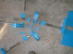
- The governor
(13) Cut the governor base plate according to governorbase.dxf, I made the baseplate for my
machine out of 3/8" mild steel, if I did it again I'd use 1/2". The reason why is that
the bearings for the blade shafts can bind under heavy load and this may interfere with
the governing action leading to overspeeding.
A 1/2" base is a lot more sturdy (it is also a bit heavier) and will prevent this
binding. Another way to improve on this part is to strengthen it by welding a piece
of angle iron left and right of the spots where the bearing support blocks will be
mounted.
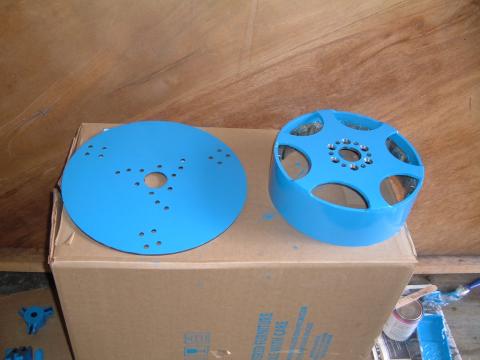
shows the governor base plate
The governor baseplate is mated to the alternator drum, the bolts go right through the
alternator drum into (4a) mounted on the main shaft.
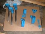
(14) The bearing support blocks (2 sets of 3)
These blocks are made out of mild steel and are shaped to receive a bronze bearing with
id 1". These bearings need lubrication and there is a little lube nipple mounted in
each of them with a channel that reaches the bearing (which has a hole mated up with the
hole in the support block).
In this image you can see the bearing support blocks on the right hand side
Originally I was going to use only three of them but later I changed the design and added
the three short blocks at the back. The short blocks are mounted with two bolts, the
longer ones (which take the brunt of the force of the blades) are mounted with 4 bolts
each.
(15) The bearings (2 sets of 3)
These are bronze bearings, 1" inner diameter with a spiral groove for lubricant. I've
sized them to sit just inside the bearing blocks (14), they're a press fit inside the
blocks.
At the pressure end (so at the rear) there is a small 1" id needle bearing that makes sure
the blade shafts (17) can rotate freely even when the mill is spinning. If there wouldn't
be a bearing here then the back of the nut that holds the shaft under tension would rub
against the stationary bearing housing. On either side of the needle bearing there is a
ring id 1", and a similar arrangement is present on the blade side. The nut at the back
end of the shaft holds the whole arrangement under very light pressure.
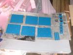
(16) The weights (set of 3)
The weights are made out of 1/4" steel sheet, according to weights.dxf and the large
shapes on linkage.dxf. They're stacked together as shown in this picture:
      And then welded up with 'invisible' welds. A 1" nut is welded onto one side of each
      weight.

 (17) The blade shafts, 1" stock shaft, welded onto (18), with a small ring welded onto the
      end

      closest to (18) so the blade mounts ride free from the bearing blocks.
      The shaft is threaded over the length from the back of the main bearing block all the way
      to the end, this thread will thread into the nut on the weight and will be used to secure
      the blade at the rear bearing block. (yes, this means that the back bearing block is
      touching the thread, which is not ideal, on the positive side the movement is very subtle
      and there is not much force on that part, it mainly helps to stabilize the shaft and to
      prevent binding of the linkage).

 (18) The blade mounts (3x)
      these are made of 2"x1" bar stock, threaded with bolt holes to accept 4 bolts on each side
      to fix the blade mounting plates. The blade mounts are welded onto the blade shafts. This
      is a *VERY* critical weld, take your time, make sure it is 100% true, check for
      deformation after welding and correct if neccesary, anneal this weld to make sure there is
      no remnant stress and avoid hardening.

 (19) The Rider
      The rider is a small tube of mild steel with a 3/4" hole in the center which will ride
      along the 3/4" threaded rod sticking out of the main shaft. It has three sets of 'ears'
      welded on to it that are used to connect the linkage (with a bolt through each hole).

 (20) The linkage (3 sets)
      The linkage connects the weights with the rider, the linkage transfers the force exerted
      by the weights and causes the rider to be pulled into the direction of the governor
      baseplate.

      The rider is pushed in the other direction by the spring that is coiled around the 3/4"
      threaded rod sticking out of the main shaft. The top of the threaded rod sticking out
      of the main shaft is stabilized by running threaded rods from the perimiter of the
      governor base plate all the way to a small steel disc at the end of the rod. You can
      also use that to connect a nose cone to protect the governor mechanism from the
      elements.

- The rotor

 (21) The Rotor Drum
      The rotor drum is 12" od tube that with 1/4" wall, 4" high. This holds the 18 magnets (23)
      in place.

 (22) The rotor drum spider
      The spider is the shape sitting at the top of the rotor drum, it connects the rotor drum
      (21) to the disc at the end of the main shaft (4a). The spider has been drilled with 12
      holes, 6 of those holes are recessed holes for bolts that will hold the rotor drum in
      place when the governor is taken off.

      The governor bolts pass right through the rotor drum spider into the holes in (4a).

 (23) The magnets
      18 2"x1"x0.5" neodymium magnets are placed at equal distances along the inside of the
      drum, aligned in such a way that each of them has about 1/4" of magnet above and below
      the stator pack.

- The blades

 (24) The blade mounting plates (set of 6)
      Size pieces of 1/4" mild steel 8"x8" drilled with holes to mate with (18) and drilled
      with a hole pattern to mate with the blades (25)

 (25) The blades, made according to the coordinates in

      https://jacquesmattheij.com/jam2.back.job
      https://jacquesmattheij.com/jam2.front.job

      Registration of front-to-back is critical, make sure that the Z axis registers
      perfect or there can be substantial variation in the shape of the blade (because it
      is very thin even the slightest change will cause huge changes in contour).

      Feel free to play with blade.py to create your own job files for your own blades.
      You will need pygame, tkinter and the scientific python package, this stuff was done
      in the dark ages (2004), chances are that you'll need to tweak things a bit to get it
      running because of changes to those packages.

      Sharp cookies will have noticed the governor.dxf file in the cad-drawings directory,
      note that that is not the design that was eventually used (the shafts were made longer
      and the a second bearing block at the back was added for more rigidity).

      In the 'plasmacutter' directory you will find a whole pile of code that can be used
      to read .job and .dxf files, to control a plasmacutter if you should have one laying
      around and to simulate a 3D gantry mill on the screen of a computer to save on
      materials.

 I'm not sure if any of that is of any use but if you should get it to work I'd like to
 hear about it. My email is jacques@modularcompany.com

 You will be able to find the files that come with this article on:

 http://jacquesmattheij.com/windmill.tar.gz (300 MB, be kind to my server, if you don't
 need it then don't download it!)

 If you find I made any mistakes above (which I surely did!) please leave the corrections
 in the comments thread on this page, that way if someone decides to follow in your
 footsteps they can save themselves some time and trouble.

 Have fun tinkering!